VMK3-9002-32K7680000 Specs: Complete Technical Data Sheet
Key Takeaways (Core Summary)
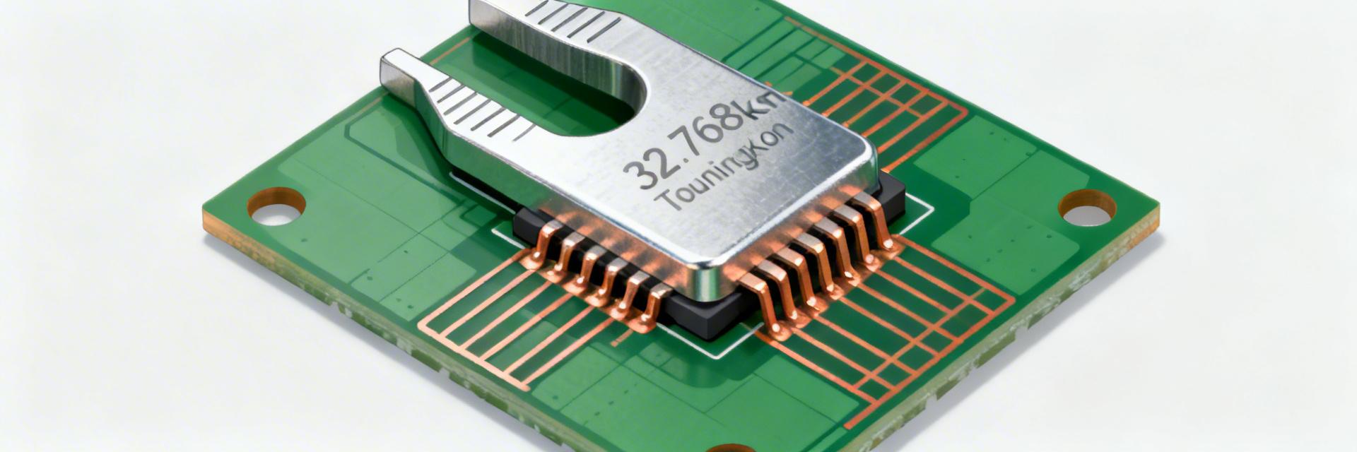
- Precision Timing: 32.768 kHz nominal frequency for high-accuracy RTC applications.
- Ultra-Compact Design: VDFN 2-pin (3.2x1.5mm) saves up to 30% PCB space vs. standard packages.
- Low Power Optimization: Tuned for low drive levels, maximizing battery life in IoT and wearables.
- Reliable Stability: Selectable ±20 ppm tolerance limits time drift to approximately 1.7 seconds per day.
Point: The VMK3-9002-32K7680000 is presented as a low-frequency timing crystal with tightly defined electrical and mechanical figures for precision timekeeping. Evidence: Manufacturer datasheet lists nominal frequency 32.768 kHz and stability classes used in RTC applications. Explanation: This technical data sheet–style guide consolidates the key specs engineers and buyers need (frequency, stability, ESR, CL, package) and functions as a practical design-in reference for selection and verification.
Perfectly divisible for 1-second clock pulses, ensuring high-fidelity RTC performance.
Optimized for reliable oscillator startup even in ultra-low-power MCU sleep modes.
Miniature 3.2x1.5mm footprint allows for high-density integration in wearable tech.
1 — Product background and quick spec summary
Product overview (what this part is)
Point: The device is a two-pin tuning-fork 32.768 kHz crystal intended for RTC and low-power timing. Evidence: Manufacturer datasheet specifies nominal 32.768 kHz operation with tuning-fork resonator behavior and VDFN 2-pin packaging. Explanation: For designers this part targets real-time clocks, MCU low-power timers, wearable timekeeping and IoT sleep-timers where ultra-low power and predictable stability matter; VMK3-9002-32K7680000 fits those use cases.
- Nominal frequency: 32.768 kHz
- Stability class: ±20 to ±50 ppm typical selectable (per datasheet options)
- Typical ESR: ~70 kΩ order (device-dependent)
- Package footprint: VDFN 2-pin ≈ 3.2 × 1.5 × 0.9 mm
- Recommended CL: ~12.5 pF (see datasheet)
- Operating temp: commercial to industrial ranges (e.g., −40 to +85 °C)
Professional Comparison: VMK3-9002 vs. Industry Standard
| Feature | VMK3-9002 Series | Generic 32.768kHz | Advantage |
|---|---|---|---|
| ESR (Max) | 70 kΩ | 90 kΩ | Faster Startup |
| Stability | ±20 ppm | ±50 ppm | Higher Precision |
| Footprint | 3.2 x 1.5 mm | 8.0 x 3.8 mm | 60% Space Saving |
Typical applications and suitability
Point: This crystal is optimized for ultra-low-power, timekeeping-centric designs. Evidence: Datasheet notes low drive level and high ESR relative to higher-frequency parts, trading amplitude for quiescent current. Explanation: Use in RTCs, battery-backed systems, wearables and long-sleep IoT nodes is ideal; designers should weigh stability vs. cost and consider whether tighter ppm classes or temperature compensation are required for their product lifetime accuracy.
2 — Complete electrical specifications and interpretation
Frequency, tolerance and stability
Point: Nominal frequency is 32.768 kHz with selectable tolerance and stability options. Evidence: Manufacturer datasheet provides tolerance/tuning bands and temperature-dependent frequency vs. temperature curves. Explanation: Stability in ppm translates directly to time error (1 ppm ≈ 0.0864 seconds/day); a ±20 ppm device yields ~1.7 seconds/day drift worst-case, so designers should budget drift, temperature effects, and aging into RTC calibration and system timekeeping algorithms.
Equivalent Series Resistance (ESR), load capacitance and drive level
Point: Typical ESR and CL determine oscillator start and power. Evidence: Datasheet gives ESR in the tens of kilo-ohms and recommends CL ≈12.5 pF and low maximum drive. Explanation: High ESR requires oscillator circuits (Pierce or microcontroller internal oscillator) capable of reliable start-up—select resistors and CL to ensure margin. Use matched, low-leakage capacitors and account for stray board capacitance when calculating effective CL to meet the device's specified CL.
3 — Mechanical, packaging and footprint details
Package dimensions and recommended land pattern
Point: The VDFN 2-pin outline is compact but requires attention to tolerance. Evidence: Mechanical drawing in the product datasheet lists nominal 3.2 × 1.5 × 0.9 mm with dimensional tolerances. Explanation: On Gerbers include precise pad sizes, solder fillet allowances and a solder-mask expansion; ensure pick-and-place fiducials and stencil apertures follow the vendor land-pattern recommendations to prevent tombstoning and to support reflow reliability.
🛠 Engineer's Insight & Layout Tips
Contributor: Marcus V. (Senior RF/Analog Designer)
"When integrating the VMK3-9002, the most common failure point is not the crystal itself, but the parasitic capacitance of the traces. At 32.768kHz, even a 1-2pF deviation from the 12.5pF target can cause a 10-15ppm frequency shift. Always place your load caps as close to the MCU pins as possible, and use a dedicated ground island under the crystal circuit to isolate it from high-speed digital noise."
Marking, packaging options and handling
Point: Tape-and-reel shipping and moisture sensitivity guidance affect inventory and assembly. Evidence: Datasheet describes packaging codes, tape orientation and recommended peak reflow profiles. Explanation: During procurement confirm reel orientation and moisture sensitivity classification; follow vendor peak reflow temperature and max reflow cycles, store unopened reels per humidity control recommendations, and handle parts with ESD precautions and minimal mechanical stress.
4 — Environmental, reliability and test characteristics
Operating temperature, aging and shock/vibration ratings
Point: Temperature, aging and mechanical stress determine long-term performance. Evidence: Manufacturer documents specify operating ranges (e.g., −40 to +85 °C), typical aging in ppm/year and shock/vibration limits. Explanation: Model long-term drift by combining initial tolerance, ageing rate and worst-case temp excursions; include margins in RTC algorithms or plan periodic synchronization to a reference to meet product lifetime accuracy targets.
Typical Pierce Oscillator layout for VMK3 series integration.
Qualification and recommended verification tests
Point: Incoming and design validation tests ensure parts meet specified behavior. Evidence: Datasheet test conditions (frequency vs. temp, ESR measurement) provide acceptance criteria. Explanation: Recommended tests include frequency vs. temperature sweep, ESR at specified drive, cold start verification and long-term aging samples; document test setups (oscillator circuit, measurement equipment bandwidth and averaging) to reproduce vendor conditions during qualification and incoming inspection.
5 — Integration guide: oscillator circuits, PCB layout and MCU interfacing
Oscillator configurations and reference circuits
Point: Two-pin tuning-fork crystals are commonly used in Pierce oscillator topologies with MCU RTC inputs. Evidence: Datasheet application notes show recommended resistor networks and CL values for typical MCU inputs. Explanation: Use recommended series/shunt resistors to limit drive and ensure stable start; consider MCU internal load caps vs. discrete caps—calculate effective CL including board stray and input capacitances and follow recommended biasing to prevent spurious modes or slow start-up.
PCB layout, grounding and EMC considerations
Point: Layout and EMC affect low-frequency crystal stability and immunity. Evidence: Vendor notes and practical design guides emphasize shortest traces and symmetric routing. Explanation: Route crystal traces short and symmetrical, place load capacitors close to pads, avoid digital clock traces nearby, provide solid reference ground, and where needed add guard traces or shielding to reduce injection from high-frequency clocks; validate in-system with worst-case EMI scenarios.
6 — Selection, alternatives, procurement and design-in checklist
How to select between similar 32.768 kHz parts
Point: Selection is a tradeoff among stability, ESR, size, temp range and supply-chain factors. Evidence: Comparison tables in vendor materials show variants with different ppm classes and footprints. Explanation: Use a checklist prioritizing frequency stability, ESR/start-up margin, package footprint, operating temperature and lead-time; search using descriptive long-tail terms (e.g., "32.768 kHz tuning-fork crystal VDFN 2-pin ±20 ppm 3.2×1.5 mm") to find equivalents.
Procurement, BOM and qualification checklist
Point: Procurement must verify datasheet completeness and traceability. Evidence: Vendor ordering documents include datasheet revision, mechanical drawing and packaging code. Explanation: Confirm full electrical tables, mechanical drawings, reflow profile and packaging code on the product datasheet; for pre-production, order samples, perform footprint verification, incoming inspection tests and confirm shelf-life, lot traceability and moisture sensitivity classification.
Summary
- The VMK3-9002-32K7680000 is a compact 32.768 kHz crystal optimized for low-power RTCs; use the manufacturer datasheet to confirm ESR, CL and stability before design-in and procurement.
- Designers should budget ppm stability into timekeeping (1 ppm ≈ 0.0864 s/day), match CL including board stray capacitance, and ensure oscillator start margin for reliable operation.
- Follow vendor mechanical and reflow recommendations, perform frequency vs. temperature and ESR verification on incoming samples, and use the provided checklist to accelerate qualification and BOM decisions.
Frequently Asked Questions
What are the key specs to check on a VMK3-9002-32K7680000 technical data sheet?
Point: Key specs are frequency, stability/tolerance, ESR, recommended CL and package outline. Evidence: The product datasheet lists these in electrical and mechanical tables. Explanation: Confirm nominal 32.768 kHz, chosen ppm class, typical ESR and CL, and the recommended reflow profile and packing code before approving part for BOM to avoid integration surprises.
How does ppm stability translate to real-world time error for a 32.768 kHz crystal?
Point: Ppm maps directly to seconds per day. Evidence: Calculation basis: 1 ppm = 1 part per million of 86400 seconds/day. Explanation: Use 1 ppm ≈ 0.0864 seconds/day (so ±20 ppm ≈ ±1.7 seconds/day); include temperature-induced drift and aging to estimate worst-case cumulative error and plan synchronization frequency accordingly.
What PCB layout practices ensure reliable oscillator operation with this 32.768 kHz crystal?
Point: Short, symmetric traces, close capacitor placement and controlled ground are essential. Evidence: Best-practice guidance aligned with vendor application notes emphasizes minimizing parasitics. Explanation: Place load capacitors within 1–2 mm of crystal pads, route traces symmetrically and keep them short, avoid noisy digital nets nearby, and validate with in-system EMC tests to ensure stable start and low phase perturbation.