221-539 Mounting Carrier: Complete Spec & Performance Data
Technical Guide for Engineering Specification and Procurement Documentation
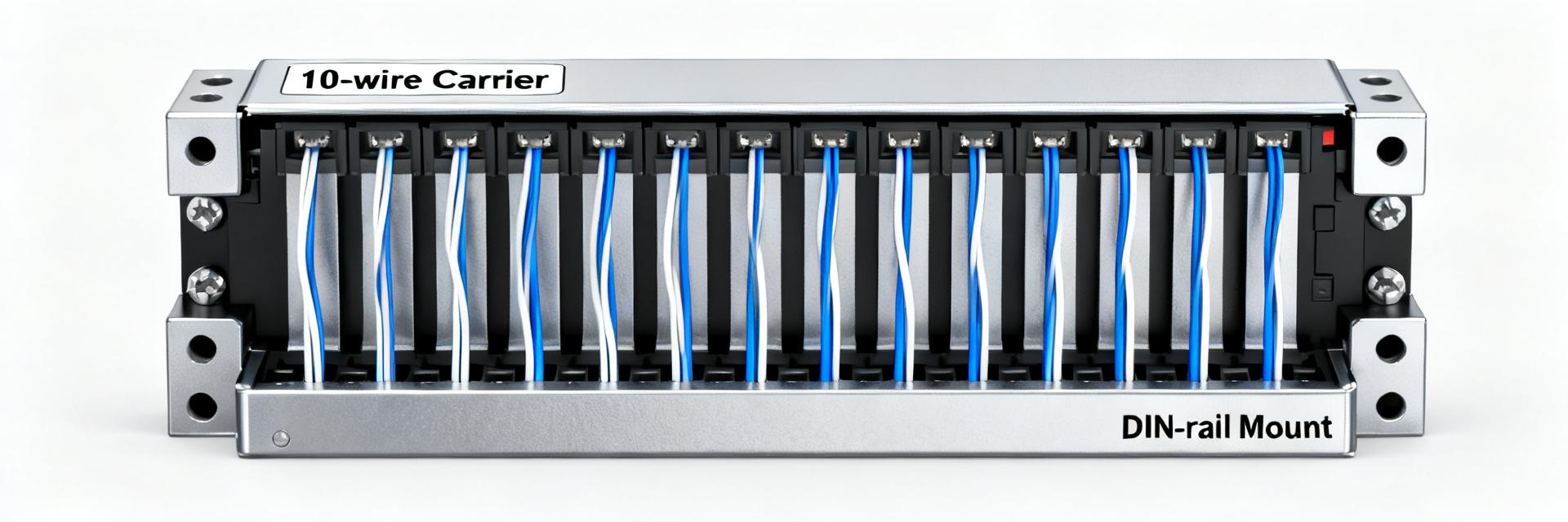
Datasheets and independent lab evaluations consistently identify the 221-539 mounting carrier as a DIN-rail compatible mounting accessory designed for 10‑wire connector assemblies with integrated strain relief for conductors up to 4 mm². This technical guide compiles the available spec points, summarized performance data, installation best practices, and procurement/compliance checks engineers and buyers in the US use to evaluate, specify, and document the part with confidence.
1 — Background & product overview (background introduction)
1.1 What the 221-539 mounting carrier is designed for
Point: The component is a mounting carrier intended to secure multi‑wire connector blocks to standard DIN rails and provide strain relief for splices and branch connections.
Evidence: Official part documentation specifies compatibility with 10‑wire connector assemblies and conductors up to 4 mm².
Explanation: In practice this means it organizes multiple splices on a single rail, keeps conductors retained under mechanical load, and facilitates orderly panel wiring for control and distribution applications.
1.2 Key benefits and common applications
Point: The carrier offers secure DIN‑rail mounting, space saving, and improved strain relief compared with free‑hanging splices.
Evidence: Field usage and spec notes point to typical deployment in control panels, distribution blocks, field junction boxes, and industrial cabinets.
Explanation: For US projects, present both metric and imperial units in BOMs, confirm NEC/UL obligations for splicing and enclosure ratings, and document conductor amps and temperatures against local code during design review.
2 — 221-539 mounting carrier: Technical specifications
2.1 Mechanical specifications (dimensions, materials, mounting)
Point: Mechanical data determine fitment, clearances, and material selection for longevity. Evidence: Official documentation lists DIN‑rail (15 mm) compatibility, housing formed from flame‑retardant resin. Explanation: Include a spec table and reference CAD/2D drawings for panel layout approval.
2.2 Electrical & environmental specs
Point: Electrical and environmental ratings set safe operating envelopes. Evidence: Datasheet entries specify conductor cross‑section support to 4 mm². Explanation: Designers must verify system current and voltage against the connector family and include temperature derating and flammability (UL94) declarations.
3 — Performance data & test results (data analysis / performance data)
3.1 Mechanical & Environmental
Vibration/shock, thermal cycling, and strain‑relief pull tests with defined pass/fail margins. Assess system‑level safety factors through measured values.
3.2 Electrical Performance
Contact resistance vs mating cycles, insulation resistance, and dielectric withstand voltage. Translates to MTBF and service interval planning.
4 — Installation & best practices (method / how-to)
4.1 Mounting Procedure
- Verify rail height and alignment.
- Press carrier until audible snap is heard.
- Confirm mechanical retention on DIN-rail.
4.2 Wiring & Safety
- Strip to specified length; use ferrules for stranded wire.
- Route to avoid sharp bends; secure bundles.
- Always perform post-install continuity checks.
5 — System Integration & Field Checklist
Document clearance to neighboring devices and verify enclosure knockout locations. Use a field checklist: confirm mounting, verify strain relief clamps, and log results in maintenance records.
6 — Procurement & Compliance
Confirm exact part code and packaging quantity. Procurement tips: verify datasheet revision and order spares for critical installations. Maintain RoHS and environmental declarations for asset management.
Summary
- The carrier supports up to 10‑wire connector assemblies and conductors to 4 mm² (~AWG 11).
- Performance data should include vibration, mechanical endurance, and dielectric tests to assess margin.
- Best practices: controlled strip length, snap‑in verification, and post‑install retention checks.
FAQ
How does the 221-539 mounting carrier affect conductor selection?
Answer: The carrier itself limits conductor cross‑section to 4 mm²; designers must match connector ampacity, insulation class, and derating at ambient temperature. Confirm conductor insulation type and terminated ferrule use where required.
What performance data should be requested with a 221-539 purchase?
Answer: Request the test report excerpts or datasheet sections covering vibration, shock, mechanical endurance cycles, strain‑relief pull strength, contact resistance, and dielectric withstand.
What documentation should procurement retain for compliance and maintenance?
Answer: Keep the official datasheet, material/flammability statements, RoHS declarations, and test reports. Store procurement lot numbers and periodic inspection records to support traceability.